In a transformer, the source of alternating current is applied to the primary winding. Due to this, the current in the primary winding (called as magnetizing current) produces alternating flux in the core of the transformer. This alternating flux gets linked with the secondary winding, and because of the phenomenon of mutual induction, an emf gets induced in the secondary winding. The magnitude of this induced emf can be found by using the following EMF equation of the transformer.
EMF Equation Of The Transformer
Let, N1 = Number of turns in primary winding N2 = Number of turns in secondary winding Φm = Maximum flux in the core (in Wb) = (Bm x A) f = frequency of the AC supply (in Hz)
As, shown in the fig., the flux rises sinusoidally to its maximum value Φm from 0. It reaches to the maximum value in one-quarter of the cycle i.e in T/4 sec (where T is time period of the sin wave of the supply = 1/f). Therefore, average rate of change of flux = Φm/(T/4) = Φm/(1/4f) Therefore, average rate of change of flux = 4f Φm ....... (Wb/s). Now, Induced emf per turn = rate of change of flux per turn
Therefore, average emf per turn = 4f Φm ..........(Volts). Now, we know, Form factor = RMS value / average value Therefore, RMS value of emf per turn = Form factor X average emf per turn.
As the flux Φ varies sinusoidally, form factor of a sine wave is 1.11
Therefore, RMS value of emf per turn = 1.11 x 4f Φm = 4.44f Φm.
RMS value of induced emf in whose primary winding (E1) = RMS value of emf per turn X Number of turns in primary winding
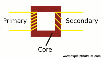
A transformer is based on a very simple fact about electricity: when a fluctuating electric current flows through a wire, it generates a magnetic field (an invisible pattern of magnetism) or "magnetic flux" all around it. The strength of the magnetism (which has the rather technical name of magnetic flux density) is directly related to the size of the electric current. So the bigger the current, the stronger the magnetic field. Now there's another interesting fact about electricity too. When a magnetic field fluctuates around a piece of wire, it generates an electric current in the wire. So if we put the second coil of wire next to the first one, and send a fluctuating electric current into the first coil, we will create an electric current in the second wire. The current in the first coil is usually called the primary current and the current in the second wire is (surprise, surprise) the secondary current. What we've done here is pass an electric current through empty space from one coil of wire to another. This is called electromagnetic induction because the current in the first coil causes (or "induces") a current in the second coil. We can make electrical energy pass more efficiently from one coil to the other by wrapping them around a soft iron bar (sometimes called a core):
To make a coil of wire, we simply curl the wire round into loops or ("turns" as physicists like to call them). If the second coil has the same number of turns as the first coil, the electric current in the second coil will be virtually the same size as the one in the first coil. But (and here's the clever part) if we have more or fewer turns in the second coil, we can make the secondary current and voltage bigger or smaller than the primary current and voltage.
One important thing to note is that this trick works only if the electric current is fluctuating in some way. In other words, you have to use a type of constantly reversing electricity called alternating current (AC) with a transformer. Transformers do not work with direct current (DC), where a steady current constantly flows in the same direction.
Step-down transformers
If the first coil has more turns than the second coil, the secondary voltage is smaller than the primary voltage:
This is called a step-down transformer. If the second coil has half as many turns as the first coil, the secondary voltage will be half the size of the primary voltage; if the second coil has one-tenth as many turns, it has one-tenth the voltage. In general:
Secondary voltage ÷ Primary voltage = Number of turns in secondary ÷ Number of turns in primary
The current is transformed the opposite way—increased in size—in a step-down transformer:
Secondary current ÷ Primary current = Number of turns in primary ÷ Number of turns in secondary
So a step-down transformer with 100 coils in the primary and 10 coils in the secondary will reduce the voltage by a factor of 10 but multiply the current by a factor of 10 at the same time. The power in an electric current is equal to the current times the voltage (watts = volts x amps is one way to remember this) so you can see the power in the secondary coil is theoretically the same as the power in the primary coil. (In reality, there is some loss of power between the primary and the secondary because some of the "magnetic flux" leaks out of the core, some energy is lost because the core heats up, and so on.)
Step-up transformers
Reversing the situation, we can make a step-up transformer that boosts a low voltage into a high one:
This time, we have more turns on the secondary coil than the primary. It's still true that:
Secondary voltage ÷ Primary voltage = Number of turns in secondary ÷ Number of turns in primary
and
Secondary current ÷ Primary current = Number of turns in primary ÷ Number of turns in secondary
In a step-up transformer, we use more turns in the secondary than in the primary to get a bigger secondary voltage and a smaller secondary current.
Considering both step-down and step-up transformers, you can see it's a general rule that the coil with the most turns has the highest voltage, while the coil with the fewest turns has the highest current.
A transformer is an electrical device that transfers electrical energy from one circuit to another by electromagnetic induction (also called transformer action). It is used to step up or step down ac voltage.
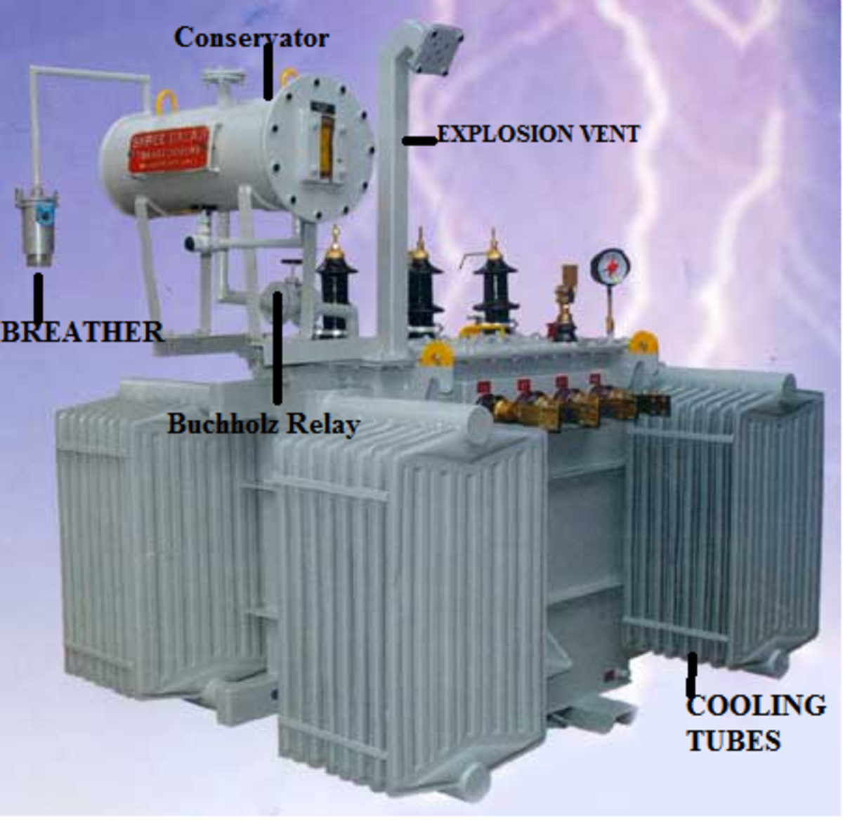
Of the above, laminated soft iron core, windings and insulating material are the primary parts and are present in all transformers, whereas the rest can be seen only in transformers having a capacity of more than 100KVA.
Core
Core
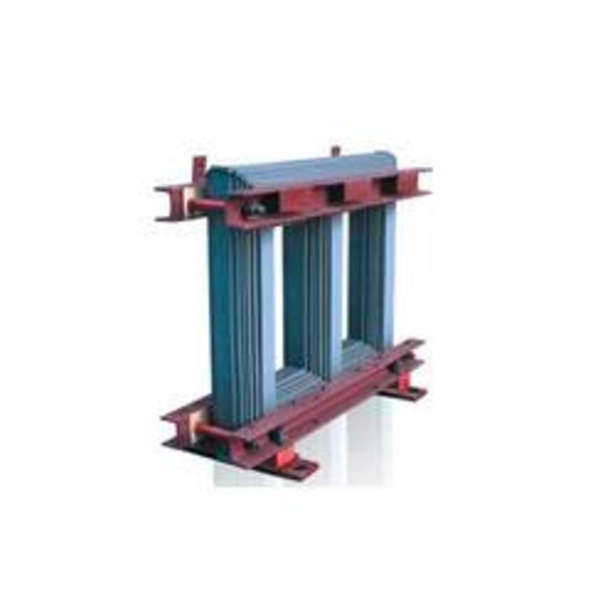
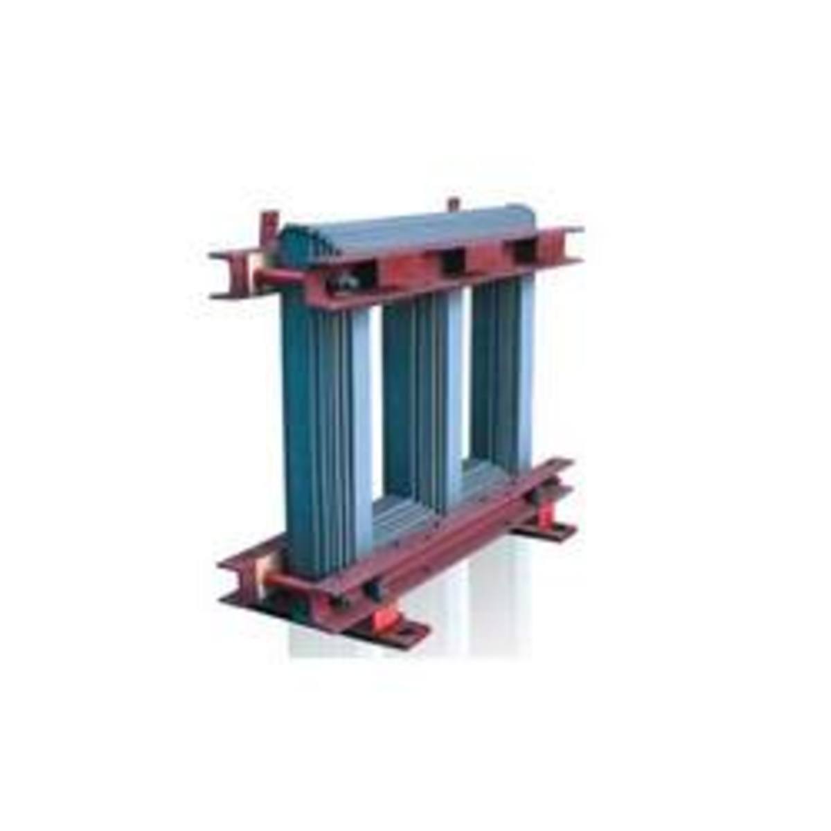
The core acts as a support to the winding in the transformer. It also provides a low reluctance path to the flow of magnetic flux. It is made of laminated soft iron core in order to reduce eddy current loss and Hysteresis loss. The composition of a transformer core depends on such as factors voltage, current, and frequency. The diameter of the transformer core is directly proportional to copper loss and is inversely proportional to iron loss. If the diameter of the core is decreased, the weight of the steel in the core is reduced, which leads to less core loss of the transformer and the copper loss increase. When the diameter of the core is increased, the vise versa occurs.
Why Are Windings Made of Copper?
Copper has high conductivity. This minimizes losses as well as the amount of copper needed for the winding (volume & weight of winding).
Copper has high ductility. This means it is easy to bend conductors into tight windings around the transformer's core, thus minimizing the amount of copper needed as well as the overall volume of the winding.
Winding
Two sets of the winding are made over the transformer core and are insulated from each other. Winding consists of several turns of copper conductors bundled together and connected in series.
Winding can be classified in two different ways:
Based on the input and output supply
Based on the voltage range
Within the input/output supply classification, winding is further categorized:
Primary winding - These are the winding to which the input voltage is applied.
Secondary winding - These are the winding to which the output voltage is applied.
Within the voltage range classification, winding is further categorized:
High voltage winding - It is made of copper conductor. The number of turns made shall be the multiple of the number of turns in the low voltage winding. The conductor used will be thinner than that of the low voltage winding.
Low voltage winding - It consists of fewer number of turns than the high voltage winding. It is made of thick copper conductors. This is because the current in the low voltage winding is higher than that of high voltage winding.
Input supply to the transformers can be applied from either low voltage (LV) or high voltage (HV) winding based on the requirement.
Insulating Materials
Insulating paper and cardboard are used in transformers to isolate primary and secondary winding from each other and from the transformer core.
Transformer oil is another insulating material. Transformer oil performs two important functions: in addition to insulating function, it can also cool the core and coil assembly. The transformer's core and winding must be completely immersed in the oil. Normally, hydrocarbon mineral oils are used as transformer oil. Oil contamination is a serious problem because contamination robs the oil of its dielectric properties and renders it useless as an insulating medium.
Parts of the Transformer
Conservator
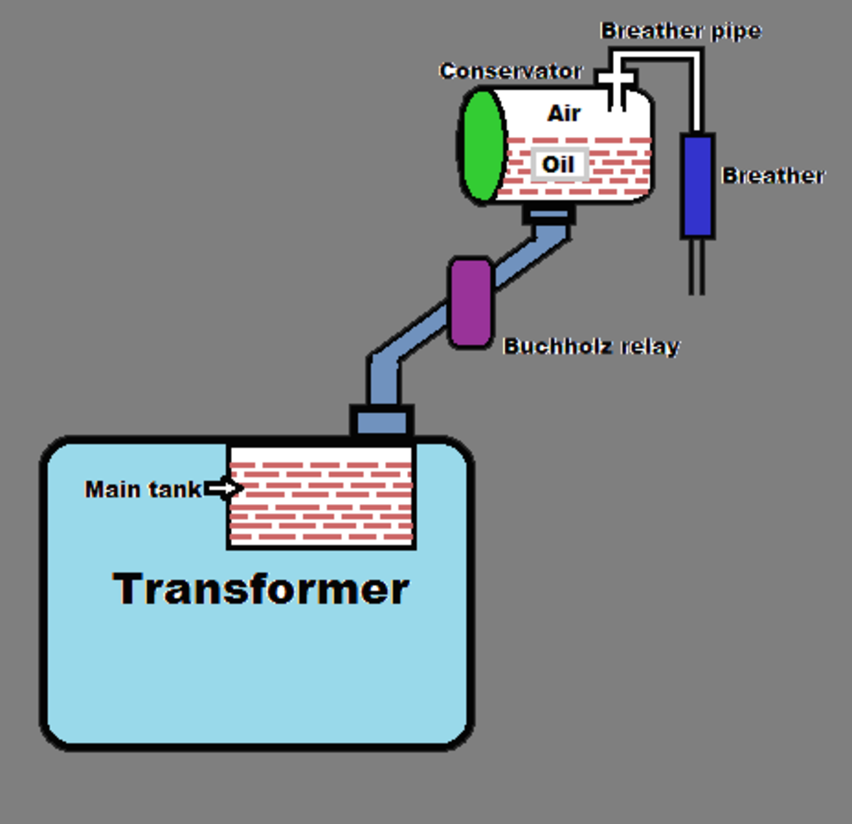
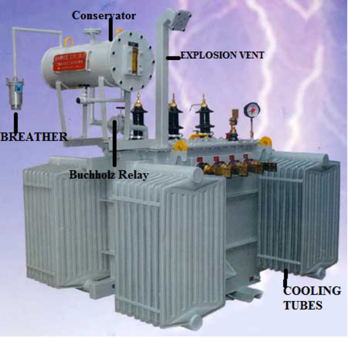
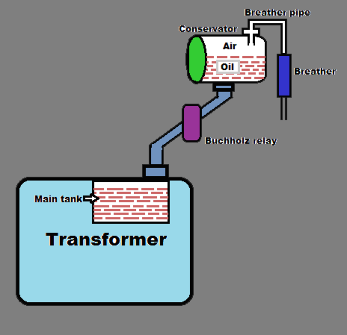
The conservator conserves the transformer oil. It is an airtight, metallic, cylindrical drum that is fitted above the transformer. The conservator tank is vented to the atmosphere at the top, and the normal oil level is approximately in the middle of the conservator to allow the oil to expand and contract as the temperature varies. The conservator is connected to the main tank inside the transformer, which is completely filled with transformer oil through a pipeline.
Breather
Breather
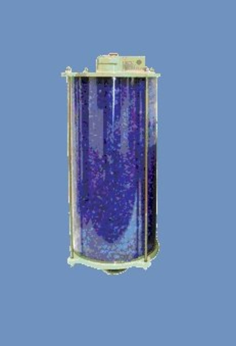
The breather controls the moisture level in the transformer. Moisture can arise when temperature variations cause expansion and contraction of the insulating oil, which then causes the pressure to change inside the conservator. Pressure changes are balanced by a flow of atmospheric air in and out of the conservator, which is how moisture can enter the system.
If the insulating oil encounters moisture, it can affect the paper insulation or may even lead to internal faults. Therefore, it is necessary that the air entering the tank is moisture-free.
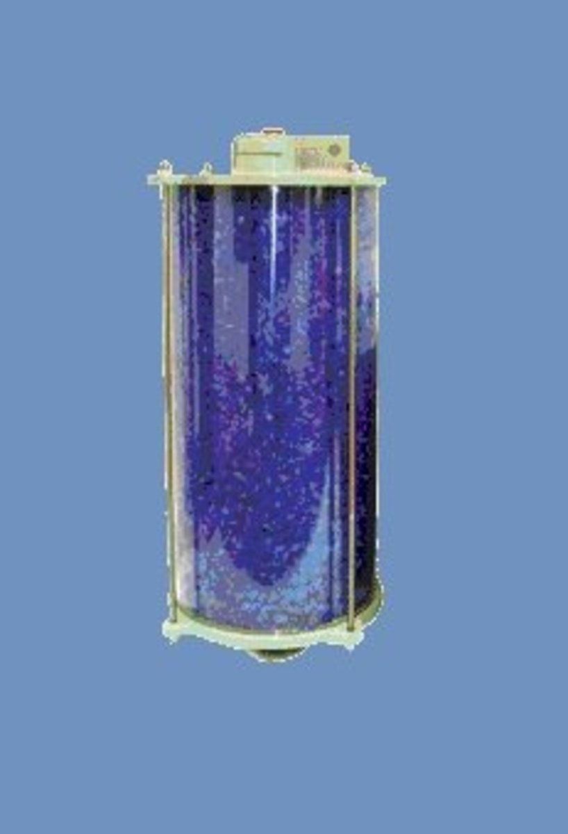
The transformer's breather is a cylindrical container that is filled with silica gel. When the atmospheric air passes through the silica gel of the breather, the air's moisture is absorbed by the silica crystals. The breather acts like an air filter for the transformer and controls the moisture level inside a transformer. It is connected to the end of breather pipe.
Tap Changer
Tap Changer
The output voltage of transformers vary according to its input voltage and the load. During loaded conditions, the voltage on the output terminal decreases, whereas during off-load conditions the output voltage increases. In order to balance the voltage variations, tap changers are used. Tap changers can be either on-load tap changers or off-load tap changers. In an on-load tap changer, the tapping can be changed without isolating the transformer from the supply. In an off-load tap changer, it is done after disconnecting the transformer. Automatic tap changers are also available.
Cooling Tubes
Cooling tubes are used to cool the transformer oil. The transformer oil is circulated through the cooling tubes. The circulation of the oil may either be natural or forced. In natural circulation, when the temperature of the oil rises the hot oil naturally rises to the top and the cold oil sinks downward. Thus the oil naturally circulates through the tubes. In forced circulation, an external pump is used to circulate the oil.
Buchholz Relay
The Buchholz Relay is a protective device container housed over the connecting pipe from the main tank to the conservator tank. It is used to sense the faults occurring inside the transformer. It is a simple relay that is operated by the gases emitted during the decomposition of transformer oil during internal faults. It helps in sensing and protecting the transformer from internal faults.
Explosion Vent
The explosion vent is used to expel boiling oil in the transformer during heavy internal faults in order to avoid the explosion of the transformer. During heavy faults, the oil rushes out of the vent. The level of the explosion vent is normally maintained above the level of the conservator tank.
More About Transformers
I have written a series of articles to help the reader understand power transformers. I've listed two here, and if you are interested in finding more, you can find them by clicking on my author profile at the top of this article.
A transformer is an electrical device that transfers electrical energy from one circuit to another by electromagnetic induction (also called transformer action). It is used to step up or step down ac voltage.
Of the above, laminated soft iron core, windings and insulating material are the primary parts and are present in all transformers, whereas the rest can be seen only in transformers having a capacity of more than 100KVA.
Core
Core
The core acts as the support to the winding of the transformer. It also provides a low reluctance path for the flow of magnetic flux. It is made of the laminated soft iron core in order to reduce eddy current loss and Hysteresis loss. The composition of a transformer core depends on such as factors voltage, current, and frequency. The diameter of the transformer core is directly proportional to copper loss and is inversely proportional to iron loss. If the diameter of the core is decreased, the weight of the steel in the core is reduced, which leads to less core loss of the transformer and the copper loss increase. When the diameter of the core is increased, the vice versa occurs.
Why Are Windings Made of Copper?
Copper has high conductivity. This minimizes losses as well as the amount of copper needed for the winding (volume & weight of winding).
Copper has high ductility. This means it is easy to bend conductors into tight windings around the transformer's core, thus minimizing the amount of copper needed as well as the overall volume of the winding.
Winding
Two sets of the winding are made over the transformer core and are insulated from each other. Winding consists of several turns of copper conductors bundled together and connected in series.
Winding can be classified in two different ways:
Based on the input and output supply
Based on the voltage range
Within the input/output supply classification, winding is further categorized:
Primary winding - These are the winding to which the input voltage is applied.
Secondary winding - These are the winding to which the output voltage is applied.
Within the voltage range classification, winding is further categorized:
High voltage winding - It is made of the copper conductor. The number of turns made shall be the multiple of the number of turns in the low voltage winding. The conductor used will be thinner than that of the low voltage winding.
Low voltage winding - It consists of the fewer number of turns than the high voltage winding. It is made of thick copper conductors. This is because the current in the low voltage winding is higher than that of high voltage winding.
Input supply to the transformers can be applied from either low voltage (LV) or high voltage (HV) winding based on the requirement.
Insulating paper and cardboard are used in transformers to isolate primary and secondary winding from each other and from the transformer core.
Transformer oil is another insulating material. Transformer oil performs two important functions: in addition to insulating function, it can also cool the core and coil assembly. The transformer's core and winding must be completely immersed in the oil. Normally, hydrocarbon mineral oils are used as transformer oil. Oil contamination is a serious problem because contamination robs the oil of its dielectric properties and renders it useless as an insulating medium.
Parts of the Transformer
Conservator
The conservator conserves the transformer oil. It is an airtight, metallic, cylindrical drum that is fitted above the transformer. The conservator tank is vented to the atmosphere at the top, and the normal oil level is approximately in the middle of the conservator to allow the oil to expand and contract as the temperature varies. The conservator is connected to the main tank inside the transformer, which is completely filled with transformer oil through a pipeline.
Breather
Breather
The breather controls the moisture level in the transformer. Moisture can arise when temperature variations cause expansion and contraction of the insulating oil, which then causes the pressure to change inside the conservator. Pressure changes are balanced by a flow of atmospheric air in and out of the conservator, which is how moisture can enter the system.
If the insulating oil encounters moisture, it can affect the paper insulation or may even lead to internal faults. Therefore, it is necessary that the air entering the tank is moisture-free.
The transformer's breather is a cylindrical container that is filled with silica gel. When the atmospheric air passes through the silica gel of the breather, the air's moisture is absorbed by the silica crystals. The breather acts like an air filter for the transformer and controls the moisture level inside a transformer. It is connected to the end of breather pipe.
Tap Changer
Tap Changer
The output voltage of transformers varies according to its input voltage and the load. During loaded conditions, the voltage on the output terminal decreases, whereas during off-load conditions the output voltage increases. In order to balance the voltage variations, tap changers are used. Tap changers can be either on-load tap changers or off-load tap changers. In an on-load tap changer, the tapping can be changed without isolating the transformer from the supply. In an off-load tap changer, it is done after disconnecting the transformer. Automatic tap changers are also available.
Cooling Tubes
Cooling tubes are used to cool the transformer oil. The transformer oil is circulated through the cooling tubes. The circulation of the oil may either be natural or forced. In natural circulation, when the temperature of the oil rises the hot oil naturally rises to the top and the cold oil sinks downward. Thus the oil naturally circulates through the tubes. In forced circulation, an external pump is used to circulate the oil.
Buchholz Relay
The Buchholz Relay is a protective device container housed over the connecting pipe from the main tank to the conservator tank. It is used to sense the faults occurring inside the transformer. It is a simple relay that is operated by the gases emitted during the decomposition of transformer oil during internal faults. It helps in sensing and protecting the transformer from internal faults.
Explosion Vent
The explosion vent is used to expel boiling oil in the transformer during heavy internal faults in order to avoid the explosion of the transformer. During heavy faults, the oil rushes out of the vent. The level of the explosion vent is normally maintained above the level of the conservatory tank.
More About Transformers
I have written a series of articles to help the reader understand power transformers. I've listed two here, and if you are interested in finding more, you can find them by clicking on my author profile at the top of this article.
Electrical Transformer is the most used electrical machine in power system. Both in the power transmission and distribution of a network, the transformer has its mandatory use.
A transformer is an electrical machine that transfers unchanged electrical energy and frequency with a modification of voltage and current between two circuits or more than two circuits. So transformer –
Does not modify the power between primary and secondary.
Does not modify the frequency of AC current or voltage.
1. To change the voltage and current level: Modern ac transmission technology requires the voltage to be higher such as 11KV, 33KV, 133Kv, 232KV. This is required to minimize the transmission loss and making the transmission line lighter, thinner hence less copper is needed. On the other hand,the consumer end voltage level is 400, 200, 120 etc. The transformer is used to step up or step down the voltage level. Also,the potential transformer is used in some protection and measurements purposes. To change the current level- Changing current level is required in some protection and measurement instruments named is a current transformer. 2. To provide galvanic isolation: Some transformer is used to isolate two circuits (no physical connection) but maintain the energy transfer by electromagnetic induction. This way both circuits can be safe from each other also different potential can be maintained. 3. To provide impedance matching: Power is unchanged in the transformer primary and secondary, only voltage and current is changed. These can be used to convert the impedance of a load to a different level. R=V/I, now say V=200, I=10 then R=20ohm; and for V=100, I=20 then R=5ohm. In both cases, the power is the same 2000Watt but impedance is varied. As per Maximum Power Transfer Theorem maximum power is transferred when the impedance is matching. Thus impedance matching mostly used in an audio system where the impedance of speaker and phone are of mismatch.
Impedance matching transformer mostly used in audio and transmitter technology.
Power transformer- used in between the power plant (power generation) up to the distribution network. Specially designed to withstand higher stress & faults in the transmission and generation network.
Distribution transformer – Used in the primary or secondary distribution network. As it is at the consumer end -specially designed for continuous service, variable load demand.
Phase shifting transformer- to control the amount flow of active power between two transmission lines.
Traction type transformer- Transformer used in the electric rail services to supply electric power to the rail or tram from the overhead electrical power cable.
Rectifier transformer or HVDC (High voltage DC transformer) – This types of the power transformer is used in high voltage DC network where there is AC network. HVDC transformer is the combination of (a) regular transformer + rectifier circuit(to convert AC to DC) in primary or secondary ; or (b)regular transformer + inverter circuit( to convert DC to AC ) in primary or secondary.
Liquid type – Transformer oil is used as a dielectric medium and also as a cooling medium. The transformer core is submerged in the transformer oil. This types of the transformer are of low cost with a disadvantage of environmental impact (transformer oil is not environment-friendly) and the possibility of a fire hazard.
Dry type transformer-Aluminum and resin is used as the structural material in dry type transformer. Both these material has the high dielectric strength and also self-cooling property. To minimize environmental contamination and fire hazard, customers are specifying dry-type transformers more frequently. Also, there is less space required, less civil work is needed. Dry type transformers are costly.
A transformer as a static device uses the electromagnetic induction principle of Faradays’ Law of Electromagnetic induction. In this case, there is no movement to get the relative motion between the constant flux and the conductor. Instead in transformer the flux is not fixed or constant but varying to get the relative effect. The transformer transfers energy from primary to secondary through electromagnetic induction. These primary and secondary windings are coupled by mutual magnetic flux. The essence of transformer action requires only the existence of time-varying mutual flux linking two windings.
An alternating voltage is connected to the primary coil. These create flux in the coil. As the voltage is alternating or time varying so is the produced flux. These time-varying flux produces induced the voltage in the secondary winding when it cuts through the secondary coil or winding.
The transformer works on the theory of Faraday’s Laws of electromagnetic induction.
The main important factor is to maintain the controlled difference between the number of primary turns and secondary turn.
The net energy transferred is same for primary circuit and secondary circuit (discarding the losses and considering that all the primary magnetic flux are associated with the secondary circuit.). Both the primary power and secondary power in the transformer is same, all is varied is the primary & secondary – voltage and current. Also, other parameters like frequency remain unchanged between primary and secondary windings.
Complete formula of transformer – taken from Wikipedia.Vp= primary voltage, Ip=primary current, Np=number of primary turn. Vs= Secondary voltage, Is=secondary current, Ns=number secondary turn. (Np/Ns)=(Vp/Vs)=(Is/Ip)
The change in voltage from primary to secondary is done by the number of coil turn variation in primary and secondary.
Transformer coil turn A transformer works on the Faraday’s law of induction, we can describe voltage and current change in the transformer by the following manner. First, we consider that all the flux from primary circuit is involved in the secondary circuit. That is there is no loss of magnetic flux, which is the case in reality for the modern design of transformer. 1. Change in voltage Now as the magnetic flux is constant what left from the Faraday’s formula is the number of turns (N) and voltage (V). The relation is “voltage varies proportionally with the number of turns. “ To increase the number of turns, the voltage will be increased. Decreased the number of turns voltage will be decreased.
2. Change in current As per Voltage and current relation, voltage and current are inversely related. If the voltage is increased then the current will be decreased and vice versa. By properly proportioning the number of primary and secondary turns, almost any desired voltage ratio, or the ratio of transformation, can be obtained.
The most important factor of the transformer is its difference between the number of turns in primary and secondary. This difference defines the transformer functional rating.
A basic transformer has the simplest construction with the primary winding set, secondary winding set, and core. The core is the medium for passing the magnetic flux from primary winding to secondary winding. Generally, iron core is used because it has higher permeability for magnetic flux. It means heat transfers better in iron than in wood and same as magnetic flux transfers or passes better in iron core then the air.
Time-varying mutual flux links both primary and secondary winding in the transformer. It is required that most of the flux is to be confined to a definite, high-permeability path linking the windings. Now with air or it is not possible but with the core of iron or other ferromagnetic material, the coupling is effectively done. Because most of the flux in the iron core is confined to a definite, high-permeability path linking the windings. [adcc]
As the iron core is also under the flux variation in transformer there is some voltage induced in the iron core. This voltage is called the eddy voltage and in result, there is a current named eddy current flow in the iron core. These results in heating up the core. With a solid iron core, the eddy current is high.
A stack of the laminated core of the transformer.To avoid this solid iron core is not used. The thin iron core is laminated to make it non-conductive. Then this thin laminated core is stacked by several to get the complete iron core structure. With this modification, eddy current is reduced but the magnetic property of the iron core remains unchanged.
To reduce the losses caused by eddy currents in the core, the magnetic circuit usually consists of a stack of thin lamination.
4. Materials of iron core of transformer-
Silicon steel for low cost, low core loss, and high permeability at high flux densities (1.0 to 1.5 T).
Compressed powdered ferromagnetic alloys known as ferrites- used in the core of small transformer used in communication circuits at high frequencies and low energy levels.

 This is called the emf equation of transformer, which shows, emf/number of turns is same for both primary and secondary winding.
 Where K = constant