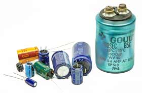
The types of capacitors available range from very small delicate trimming capacitors using an oscillator or radio circuits, up to large power metal-can type capacitors used in high voltage power correction and smoothing circuits.
The comparisons between the different types of the capacitor are generally made with regards to the dielectric used between the plates. Like resistors, there are also various types of capacitors which allow us to vary their capacitance value for use in radio or “frequency tuning” type circuits.
Commercial types of capacitors are made from metallic foil interlaced with thin sheets of either paraffin-impregnated paper or Mylar as the dielectric material. Some capacitors look like tubes, this is because the metal foil plates are rolled up into a cylinder to form a small package with the insulating dielectric material sandwiched in between them.
Small capacitors are often constructed from ceramic materials and then dipped into an epoxy resin to seal them. Either way, capacitors play an important part in electronic circuits so here are a few of the more “common” types of capacitor available.
Dielectric Capacitor
Dielectric Capacitors are usually of the variable type were a continuous variation of capacitance is required for tuning transmitters, receivers, and transistor radios. Variable dielectric capacitors are multi-plate air-spaced types that have a set of fixed plates (the stator vanes) and a set of movable plates (the rotor vanes) which move in between the fixed plates.
The position of the moving plates with respect to the fixed plates determines the overall capacitance value. The capacitance is generally at a maximum when the two sets of plates have fully meshed together. High voltage type tuning capacitors have relatively large spacings or air-gaps between the plates with breakdown voltages reaching many thousands of volts.
Variable Capacitor Symbols
As well as the continuously variable types, preset type variable capacitors are also available called Trimmers. These are generally small devices that can be adjusted or “pre-set” to a particular capacitance value with the aid of a small screwdriver and are available in very small capacitance’s of 500pF or less and are non-polarized.
Film Capacitor
Film Capacitors are the most commonly available of all types of capacitors, consisting of a relatively large family of capacitors with the difference being in their dielectric properties. These include polyester (Mylar), polystyrene, polypropylene, polycarbonate, metalized paper, Teflon etc. Film type capacitors are available in capacitance ranges from as small as 5pF to as large as 100uF depending upon the actual type of capacitor and its voltage rating. Film capacitors also come in an assortment of shapes and case styles which include:
Wrap & Fill (Oval & Round) – where the capacitor is wrapped in a tight plastic tape and have the ends filled with epoxy to seal them.
Epoxy Case (Rectangular & Round) – where the capacitor is encased in a molded plastic shell which is then filled with epoxy.
Metal Hermetically Sealed (Rectangular & Round) – where the capacitor is encased in a metal tube or can and again sealed with epoxy.
with all the above case styles available in both Axial and Radial Leads.
Film Capacitors which use polystyrene, polycarbonate or Teflon as their dielectrics are sometimes called “Plastic capacitors”. The construction of plastic film capacitors is similar to that for paper film capacitors but use a plastic film instead of paper. The main advantage of plastic film capacitors compared to impregnated-paper types is that they operate well under conditions of high temperature, have smaller tolerances, a very long service life, and high reliability. Examples of film capacitors are the rectangular metalized film and cylindrical film & foil types as shown below.
Radial Lead Type
Axial Lead Type
The film and foil types of capacitors are made from long thin strips of thin metal foil with the dielectric material sandwiched together which are wound into a tight roll and then sealed in paper or metal tubes.
Film Capacitor
These film types require a much thicker dielectric film to reduce the risk of tears or punctures in the film and is, therefore, more suited to lower capacitance values and larger case sizes.
Metalised foil capacitors have the conductive film metalized sprayed directly onto each side of the dielectric which gives the capacitor self-healing properties and can, therefore, use much thinner dielectric films. This allows for higher capacitance values and smaller case sizes for a given capacitance. Film and foil capacitors are generally used for higher power and more precise applications.
Ceramic Capacitors
Ceramic Capacitors or Disc Capacitors as they are generally called, are made by coating two sides of a small porcelain or ceramic disc with silver and are then stacked together to make a capacitor. For very low capacitance values a single ceramic disc of about 3-6mm is used. Ceramic capacitors have a high dielectric constant (High-K) and are available so that relatively high capacitances can be obtained in a small physical size.
Ceramic Capacitor
They exhibit large non-linear changes in capacitance against temperature and as a result are used as de-coupling or by-pass capacitors as they are also non-polarized devices. Ceramic capacitors have values ranging from a few picofarads to one or two microfarads, ( μF ) but their voltage ratings are generally quite low.
Ceramic types of capacitors generally have a 3-digit code printed onto their body to identify their capacitance value in pico-farads. Generally, the first two digits indicate the capacitors value and the third digit indicates the number of zeroes to be added. For example, a ceramic disc capacitor with the markings 103would indicate 10 and 3 zero’s in pico-farads which is equivalent to 10,000 pF or 10nF.
Likewise, the digits 104 would indicate 10 and 4 zero’s in pico-farads which is equivalent to 100,000 pF or 100nF and so on. Soon the image of the ceramic capacitor above the numbers 154 indicate 15 and 4 zero’s in pico-farads which is equivalent to 150,000 pF or 150nF or 0.15uF. Letter codes are sometimes used to indicate their tolerance value such as: J = 5%, K = 10% or M = 20% etc.
Electrolytic Capacitors
Electrolytic Capacitors are generally used when very large capacitance values are required. Here instead of using a very thin metallic film layer for one of the electrodes, a semi-liquid electrolyte solution in the form of a jelly or paste is used which serves as the second electrode (usually the cathode).
The dielectric is a very thin layer of oxide which is grown electrochemically in production with the thickness of the film being less than ten microns. This insulating layer is so thin that it is possible to make capacitors with a large value of capacitance for a small physical size as the distance between the plates, d is very small.
Electrolytic Capacitor
The majority of electrolytic types of capacitors are Polarised, that is the DC voltage applied to the capacitor terminals must be of the correct polarity, i.e. positive to the positive terminal and negative to the negative terminal as an incorrect polarisation will break down the insulating oxide layer and permanent damage may result.
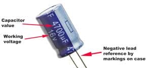
All polarised electrolytic capacitors have their polarity clearly marked with a negative sign to indicate the negative terminal and this polarity must be followed.
Electrolytic Capacitors are generally used in DC power supply circuits due to their large capacitance’s and small size to help reduce the ripple voltage or for coupling and decoupling applications. One main disadvantage of electrolytic capacitors is their relatively low voltage rating and due to the polarisation of electrolytic capacitors, it follows then that they must not be used on AC supplies. Electrolytic’s generally come in two basic forms; Aluminium Electrolytic Capacitors and Tantalum Electrolytic Capacitors.
Electrolytic Capacitor
1. Aluminium Electrolytic Capacitors
There are basically two types of Aluminium Electrolytic Capacitor, the plain foil type, and the etched foil type. The thickness of the aluminum oxide film and high breakdown voltage give these capacitors very high capacitance values for their size.
The foil plates of the capacitor are anodized with a DC current. This anodizing process sets up the polarity of the plate material and determines which side of the plate is positive and which side is negative.
The etched foil type differs from the plain foil type in that the aluminum oxide on the anode and cathode foils has been chemically etched to increase its surface area and permittivity. This gives a smaller sized capacitor than a plain foil type of equivalent value but has the disadvantage of not being able to withstand high DC currents compared to the plain type. Also, their tolerance range is quite large at up to 20%. Typical values of capacitance for an aluminum electrolytic capacitor range from 1uF up to 47,000uF.
Etched foil electrolytic’s are best used in coupling, DC blocking and by-pass circuits while plain foil types are better suited as smoothing capacitors in power supplies. But aluminum electrolytic’s are “polarised” devices so reversing the applied voltage on the leads will cause the insulating layer within the capacitor to become destroyed along with the capacitor. However, the electrolyte used within the capacitor helps heal a damaged plate if the damage is small.
Since the electrolyte has the properties to self-heal a damaged plate, it also has the ability to re-anodize the foil plate. As the anodizing process can be reversed, the electrolyte has the ability to remove the oxide coating from the foil as would happen if the capacitor was connected to a reverse polarity. Since the electrolyte has the ability to conduct electricity, if the aluminum oxide layer was removed or destroyed, the capacitor would allow current to pass from one plate to the other destroying the capacitor, “so be aware”.
2. Tantalum Electrolytic Capacitors
Tantalum Electrolytic Capacitors and Tantalum Beads, are available in both wet (foil) and dry (solid) electrolytic types with the dry or solid tantalum being the most common. Solid tantalum capacitors use manganese dioxide as their second terminal and are physically smaller than the equivalent aluminum capacitors.
The dielectric properties of tantalum oxide are also much better than those of aluminum oxide giving a lower leakage current and better capacitance stability which makes them suitable for use in blocking, by-passing, decoupling, filtering and timing applications.
Also, Tantalum Capacitors although polarised, can tolerate being connected to a reverse voltage much more easily than the aluminum types but are rated at much lower working voltages. Solid tantalum capacitors are usually used in circuits where the AC voltage is small compared to the DC voltage.
However, some tantalum capacitor types contain two capacitors in-one, connected negative-to-negative to form a “non-polarised” capacitor for use in low voltage AC circuits as a non-polarised device. Generally, the positive lead is identified on the capacitor body by a polarity mark, with the body of a tantalum bead capacitor being an oval geometrical shape. Typical values of capacitance range from 47nF to 470uF.
Aluminium & Tantalum Electrolytic Capacitor
Electrolytic’s are widely used capacitors due to their low cost and small size but there are three easy ways to destroy an electrolytic capacitor:
Over-voltage – excessive voltage will cause current to leak through the dielectric resulting in a short circuit condition.
Reversed Polarity – reverse voltage will cause self-destruction of the oxide layer and failure.
Over Temperature – excessive heat dries out the electrolytic and shortens the life of an electrolytic capacitor.
In the next tutorial about Capacitors, we will look at some of the main characteristics to show that there is more to the Capacitor than just voltage and capacitance.
-key equations and calculations for capacitors and capacitance in electronics circuits including reactance, charge, value, etc.
There are many calculations and equations associated with capacitors. The capacitor reactance equations and calculations are common, but there are many more capacitor calculations that may need to be performed.
Capacitor equations and capacitor calculations include many aspects of capacitor operation including the capacitor charge, capacitor voltage capacitor reactance calculations and many more.
The very basic capacitor equations link the capacitance with the charge held on the capacitor, and the voltage across the plates.
where C is the capacitance in Farads Q is the charge held on the plates in coulombs V is the potential difference between the plates in volts
This equation can then be developed to calculate the work required for charging a capacitor, and hence the energy stored in it.
Capacitor reactance formula
In a direct current circuit where there may be a battery and a resistor, it is the resistor that resists the flow of current in the circuit. This is basic Ohms Law. The same is true for an alternating current circuit with a capacitor. A capacitor with a small plate area will only be able to store a small amount of charge, and this will impede the flow of current. A larger capacitor will allow a greater flow of current. A capacitor is said to have a certain reactance. This name is chosen to be different to that of a resistor, but it is measured in Ohms just the same. The reactance of a capacitor is dependent upon the value of the capacitor and also the frequency of operation. The higher the frequency the smaller the reactance.
The actual reactance can be calculated from the formula:
where Xc is the capacitive reactance in ohms f is the frequency in Hertz C is the capacitance in Farads
Current calculations
The reactance of the capacitor that is calculated from the formula above is measured in Ohms. The current flowing in the circuit can then be calculated in the normal way using Ohms Law:
Adding resistance and reactance
Although resistance and reactance are very similar, and the values of both are measured in Ohms, they are not exactly the same. As a result, it is not possible to add them together directly. Instead, they have to be summed "vectorially". In other words, it is necessary to square each value, and then add these together and take the square root of this figure. Put in a more mathematical format:
where Xtot is the total impedance in ohms Xc is the capacitive reactance in ohms R is the DC resistance in ohms
It is particularly important to select the right capacitor or any given application - understanding the key requirements for any given capacitor application or capacitor use will ensure the circuit operates correctly.
Capacitors are used in virtually every area of electronics, and they perform a variety of different tasks. Although capacitors operate in the same way whatever the capacitor application or use, there are several different uses for capacitors in circuits.
In order to select the right kind of capacitor, it is necessary to have an understanding of the particular capacitor application so that its properties can be matched to the given user to which it is to be put.
Each form of the capacitor has its own attributes and this means that it will perform well in a particulate capacitor use or application.
Choosing the right capacitor for a given application is all part of the design process for a circuit. Using the wrong capacitor can easily mean that a circuit will not work.
Capacitors can be used in a variety of different ways in electronics circuits. Although their mode of operation remains exactly the same, the different forms of the capacitor can be used to provide a variety of different circuit functions.
Coupling capacitor use
In this capacitor application, the component allows AC signals to pass from one section of a circuit to another while blocking any DC static voltage. This form of capacitor application is often required when connecting two stages of an amplifier together.
It is possible that a static voltage will be present, say on the output of one stage, and only the alternating signal, audio frequency, radio frequency or whatever is required. If the DC components of the signal at the output of the first stage were present at the input of the second, then the bias and other operating conditions of the second stage would be altered.
Transistor circuit with input and output coupling capacitors
Even when using operational amplifiers where the circuit has been designed to provide small offset voltages, it is often wise to use coupling capacitors because of the high levels of DC gain present. Without a coupling capacitor, the high levels of DC gain could mean that the operational amplifier would run into saturation.
For capacitor applications of this nature, it is necessary to ensure that the impedance of the capacitor is sufficiently low. Typically the value of the capacitor is chosen to be the same as the impedance of the circuit, normally the input impedance of the second circuit. This gives a drop in the response of 3dB at this frequency.
IMPORTANT PARAMETERS FOR COUPLING CAPACITOR USES
PARAMETER
NOTES ON CAPACITOR USE
Capacitor rated voltage
Must be greater than the peak voltage across the capacitor. Normally the capacitor will be able to withstand the supply rail voltage with margin in hand to ensure reliability.
Capacitance value
High enough to pass lowest frequencies with little or no attenuation.
Tolerance
Wide tolerance capacitors can often be used because the exact value is not important.
Dielectric
Some capacitors, for example, electrolytic capacitors have a limited frequency response. This should be taken into account. Also for high impedance applications, electrolytic capacitors should not be used as they have a relatively high level of leakage which may offset the operation of the second stage.
Decoupling capacitor use
In this application, the capacitor is used to remove any AC signals that may be on a DC bias point, power rail, or another node that needs to be free of a particular varying signal.
As the name of this capacitor use indicates, it used to decouple the node from the varying signal on it.
Transistor circuit with line and collector decoupling capacitors
In this circuit, there are two ways in which the capacitor is used for decoupling. C3 is used to decouple any signal that may be on the voltage rail. Also the combination C4, R5 is used to ensure that the collector signal does not leak through on the signal rail. The time constant of C4 and R5 is generally the dominating factor and the time constant should be chosen to be longer than the lowest frequency anticipated.
IMPORTANT PARAMETERS FOR DECOUPLING CAPACITOR USES
PARAMETER
NOTES ON CAPACITOR USE
Capacitor rated voltage
Must be greater than the peak voltage across the capacitor. Normally the capacitor will be able to withstand the voltage of the node with some margin in hand to ensure reliability.
Capacitance value
High enough to pass lowest frequencies with little or no attenuation.
Tolerance
Wide tolerance capacitors can often be used because the exact value is not important.
Dielectric
Some capacitors like electrolytic capacitors have a relatively low upper-frequency limit. Often to overcome this, a capacitor such as a ceramic capacitor with a smaller value may be used to provide the high-frequency response, while a larger value electrolytic capacitor is used to pass the lower frequency components. The lower value ceramic or another capacitor still presents a low impedance at the higher frequencies because the reactive impedance is inversely proportional to the frequency.
RF coupling and decoupling applications
When using capacitors for RF applications, it is necessary to consider their RF performance. This can be different to the performance at lower frequencies. Performance issues like self-resonance, low tangent and the like become particularly important. At microwave frequencies, the issue can be of great importance.
Many surface mount ceramic capacitors offer very good performance levels and these are often used.
Smoothing capacitor applications
This is effectively the same as a decoupling capacitor, but the term is normally used in conjunction with a power supply.
When an incoming line signal is taken through a transformer and a rectifier, the resulting waveform is not smooth. It varies between zero and the peak voltage. If applied to a circuit, this is most unlikely to operate as a DC voltage is normally needed. To overcome this, a capacitor is used to decouple or smooth the output voltage.
Rectifier circuit with smoothing capacitor
In this use, the capacitor charges up when the peak voltage exceeds that of the output voltage, and supplies charge when the rectifier voltage falls below the capacitor voltage.
In this capacitor use, the component decouples the rail and supplies charge where needed.
IMPORTANT PARAMETERS FOR SMOOTHING CAPACITOR USES
PARAMETER
NOTES ON CAPACITOR USE
Capacitor rated voltage
Must be greater than the peak voltage across the capacitor. The capacitor must be able to withstand the maximum peak rail voltage with some margin in hand to ensure reliability.
Capacitance value
Dependent upon the current required, but typically can be several thousand microfarads.
Tolerance
Wide tolerance capacitors can often be used because the exact value is not important.
Dielectric
Electrolytic capacitors are typically used because of the high values available.
Ripple current
In addition to the capacitor having sufficient capacitance to hold the required amount of charge, t must also be constructed in a way to be able to supply the current required. If the capacitor becomes too hot when delivering the current it may be damaged and fail. Ripple current ratings are particularly important on capacitors used for smoothing applications.
Capacitor use as a timing element
In this application, a capacitor can be used with a resistor or inductor in a resonant or time-dependent circuit. In this function, the capacitor may appear in a filter, oscillator tuned circuit, or in a timing element for a circuit such as an a-stable, the time it takes to charge and discharge determining the operation of the circuit
LC or RC oscillators and filters are widely used in a host of circuits, and obviously one of the major elements is the capacitor.
In this particular capacitor use, one of the main requirements is for accuracy, and therefore the initial tolerance is important to ensure that the circuit operates on the required frequency. Temperature stability is also important to ensure that the performance of the circuit remains the same over the required temperature range.
IMPORTANT PARAMETERS FOR TIMING CAPACITOR USES
PARAMETER
NOTES ON CAPACITOR USE
Capacitor rated voltage
The actual peak voltage across the capacitor will vary according to the particular circuit and the rail voltage. It is necessary to assess each case on its own merits, noting that in some cases it may be higher than expected. In most cases, it is unlikely to exceed the rail voltage.
Capacitance value
Dependent upon the frequencies used and the inductor or resistor needed to obtain the required operating frequency.
Tolerance
Close tolerance normally needed to ensure that the required operating frequency is obtained. In this application, capacitors with a good selection of values within each decade may be an advantage.
Dielectric
In many timing applications, the capacitor loss is important. High loss equates to low Q, and Q values should normally be as high as possible.
Temperature stability
The temperature stability of the capacitor should be high for these capacitor applications because the circuit will need to retain its frequency over the operating temperature range. If the value changes with temperature, even by a small amount, this can have a marked effect on the operation of the circuit.
Hold-up capacitor applications
In this particular capacitor application, the charge held by the capacitor is used to provide power for a circuit for a short while.
IMPORTANT PARAMETERS FOR HOLD-UP CAPACITOR USES
PARAMETER
NOTES ON CAPACITOR USE
Capacitor rated voltage
Must be able to withstand the maximum operating voltage with a good margin for reliability.
Capacitance value
Can be up to several Farads.
Tolerance
Super capacitors widely used for this capacitor application have a wide tolerance. Fortunately this is not an issue as it primarily affects the time the hold-up can be maintained.
Supercapacitors are often used for battery hold up applications
Capacitor application choices
In addition to the function within a circuit, there is also the frequency of operation that is of importance. Some capacitors operate better at low frequencies, whereas others are better at high or radio frequencies.
Capacitors are used in virtually every electronics circuit that is built today. Capacitors are manufactured in their millions each day, but there are several different capacitor types that are available.
Each type of capacitor has its own advantages and disadvantages can be used in different applications.
Accordingly, it is necessary to know a little about each capacitor type so that the correct one can be chosen for any given use or application.
Capacitor types
There are very many different capacitor types that can be bought and used in electronics circuits.
While the list below gives some of the major capacitor types, not all can be listed and described and there are some less well used or less common types that can be seen. However, it does include most of the major capacitor types.
Ceramic capacitor: As the name indicates, this type of capacitor gains its name from the fact that it uses a ceramic dielectric. This gives the many properties including a low loss factor, and a reasonable level of stability, but this depends upon the exact type of ceramic used. Ceramic dielectrics do not give as high a level of capacitance per unit volume as some types of capacitor and as a result ceramic capacitors typically range in value from a few picofarads up to values around 0.1 µF.
For leaded components, disc ceramic capacitors are widely used. This type of ceramic capacitor is extensively for applications like decoupling and coupling applications. More highly specified capacitors, especially used in surface mount types of capacitor often have specific types of ceramic dielectric specified. The more commonly seen types include:
COG: Normally used for low values of capacitance. It has a low dielectric constant but gives a high level of stability.
X7R: Used for higher capacitance levels as it has a much higher dielectric constant than COG, but a lower stability.
Z5U: Used for even higher values of capacitance, but has a lower stability than either COG or X7R.
Electrolytic capacitor: This type of capacitor is the most popular leaded type for values greater than about 1 microfarad, having one of the highest levels of capacitance for a given volume. This type of capacitor is constructed using two thin films of aluminum foil, one layer being covered with an oxide layer as an insulator. An electrolyte-soaked paper sheet is placed between them and then the two plates are wound around on one another and then placed into a can.
Electrolytic capacitors are polarised, i.e. they can only be placed one way round in the circuit. If they are connected incorrectly they can be damaged, and in some extreme instances, they can explode. Care should also be taken not to exceed the rated working voltage. Normally they should be operated well below this value.
This capacitor type has a wide tolerance. Typically the value of the component may be stated with a tolerance of -50% +100%. Despite this, they are widely used in audio applications as coupling capacitors, and in smoothing applications for power supplies. They do not operate well at high frequencies and are typically not used for frequencies above 50 - 100 kHz. . . . . Read more about electrolytic capacitors.
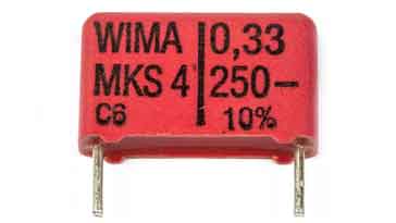
Plastic film capacitors: There are two main formats for the construction of plastic film capacitors:
Metallised film: In this type of film capacitor the plastic film has a very thin layer of metallisation deposited into the film. This realisation is connected to the relevant connection on one side of the capacitor or the other.
Film foil: This form of film capacitor has two metal foil electrodes that are separated by the plastic film. The terminals are connected to the end-faces of the electrodes by means of welding or soldering.
Plastic film capacitors can use a variety of dielectrics. Polycarbonate, polyester, and polystyrene are some of the most common. Each has its own properties, allowing them to be used in specific applications. Their values may range anywhere from several picofarads to a few microfarads dependent upon the actual type. Polyester film capacitorNormally they are non-polar. In general, they are good general-purpose capacitors that may be used for a variety of purposes, although their high-frequency performance is not usually as good as that of the ceramic types. Some of the more common types include:
Mylar - Can introduce noise when used in applications where there is vibration.
Polycarbonate - Moderate level of loss which can increase with frequency. Very high insulation resistance.
Polyester - Moderate level of loss which can increase with frequency. Very high insulation resistance.
Polystyrene - tend to be a very low loss but bulky. Have a temperature coefficient of around -150 ppm / C
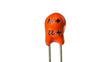
Tantalum: Ordinary aluminum electrolytic capacitors are rather large for many uses. In applications where size is of importance, tantalum capacitors may be used. These are much smaller than the aluminum electrolytic and instead of using a film of oxide on aluminum they us a film of oxide on tantalum. They do not normally have high working voltages, 35V is normally the maximum, and some even have values of only a volt or so.
Leaded tantalum capacitorLike electrolytic capacitors, tantalums are also polarised and they are very intolerant of being reversely biased, often exploding when placed under stress. However, their small size makes them very attractive for many applications. . . . . Read more about tantalum capacitors.
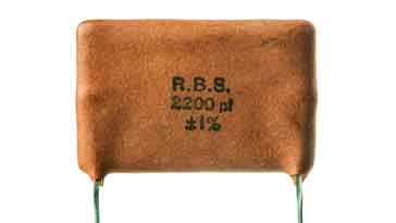
Silver Mica: Silver mica capacitors are manufactured by plating silver electrodes directly on to the mica film dielectric. To achieve the required capacitance, several layers are used. Wires for the connections are added and then the whole assembly is encapsulated. The values of silver mica capacitors range in value from a few picofarads up to two or three thousand picofarads. Silver mica capacitorThis type of capacitor is not as widely used these days. However, they can still be obtained and are used where stability of value is of the utmost importance and where low loss is required. In view of this one of their major uses is within the tuned elements of circuits like oscillators, or within filters. . . . . Read more about silver mica capacitors.
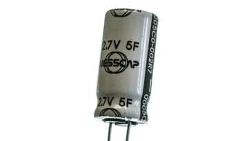
Supercap Supercapacitors with capacitance levels of a Farad or more are now becoming more commonplace. These supercapacitors are generally used for applications like memory hold up and the like. Supercapacitor or supercapThey are too large for use in most circuits and their frequency response is limited, but they make ideal hold up capacitors, being able to provide residual current and voltage to retain memory for periods when power may be removed. . . . . Read more about supercapacitors.
Capacitor types overview
It can be seen from even the selection of the most commonly used types of capacitor, that many forms are available. Each has its own advantages and disadvantages, and if the right one is chosen for each job, then it can perform very well in a circuit. It is for this reason when building circuits that it is important to use the right type of capacitor. If the wrong sort is used, then its performance may not be the standard needed for the circuit.
The electrolytic capacitor is one of the mainstays of the capacitor industry.
The electrolytic capacitor is the most popular leaded type for values greater than about 1 µF, having one of the highest levels of capacitance for a given volume.
Aluminium electrolytic capacitors have been in use for many years - in this way they have become a regular component in many designs.
Electrolytic capacitors are widely used as leaded components, often being found in applications from power supplies to audio where leaded devices can be used. Initially, aluminium electrolytic capacitors were not popular in surface mount technology format because of the levels of heat experienced during soldering could damage them. Now with more development, surface mount electrolytic capacitors are widely used and provide good levels of reliability.
Electrolytic capacitor early development
The electrolytic capacitor has been in use for many years. Its early development and history can be traced back to the very early days or radio around the time when the first broadcasts of entertainment were being made. At the time, valve wireless sets were very expensive, and they had to run from batteries. However, with the development of the indirectly heated valve or vacuum tube, it became possible to use AC mains power.
While it was fine for the heaters to run from an AC supply, the anode supply needed to be rectified and smoothed to prevent mains hum appearing on the audio. In order to be able to use a capacitor that was not too large Julius Lilienfield who was heavily involved in developing wireless sets for domestic use was able to develop the electrolytic capacitor, allowing a component with sufficiently high capacitance but reasonable size to be used in the wireless sets of the day.
Electrolytic capacitor symbols
An electrolytic capacitor is a form of a polarised capacitor. The electrolytic circuit symbol indicates the polarity as it is essential to ensure that the capacitor is fitted into the circuit correctly and is not reverse biased.
Circuit symbol variants used for electrolytic capacitors
There is a variety of schematic symbols used for electrolytic capacitors. The first one '1' is the version that tends to be used in European circuit diagrams, while '2' is used in many US schematics, and '3' may be seen on some older schematics. Some schematic diagrams do not print the "+" adjacent to the symbol where it is already obvious which plate is which.
Electrolytic capacitor construction
This type of capacitor is constructed using two thin films of aluminum foil, one layer being covered with an oxide layer as an insulator. The use of the aluminum foil gives rise to the fact that the capacitor is often referred to as the aluminum electrolytic capacitor.
An electrolyte-soaked paper sheet is placed between them and then the two plates are wound around on one another and then placed into a can.
Selection of leaded aluminum electrolytic capacitors
In the manufacture of the aluminum electrolytic capacitor, one of the first stages is to etch the foils to make them rougher to increase the surface area and hence the capacitance level that can be gained in a given area.
The next process is to form the anode. This entails chemically growing a thin layer of aluminum oxide, Al2O3onto the anode foil making it different from the cathode.
The capacitor element itself is wound on a winding machine. The four separate layers: the formed anode foil; paper separator, cathode foil; and paper separator are all brought in and wound together. The paper separators prevent the two electrodes from touching and shorting.
Electrolytic capacitor construction
When the assembly has been wound, it is taped to prevent unwinding.
Once the capacitor is wound, it is impregnated with the electrolyte. This may be done by immersion and under pressure.
The electrolyte used in aluminum electrolytic capacitors is a formulation developed to provide the required properties for the capacitor - voltage rating, operating temperature range and the like. It primarily consists of solvent and a salt (required to provide the electrical conduction). Common solvents include ethylene glycol, and common salt includes ammonium borate and other ammonium salts.
Once this is complete the capacitor is placed into a can which is sealed to prevent evaporation of the electrolyte.
Electrolytic capacitor properties
Aluminium electrolytic capacitors provide a much higher level of capacitance for a given volume than most ceramic capacitors. This means that high-value electrolytic capacitors can be relatively small. This is a significant advantage in many instances.
Markings on aluminum electrolytic capacitor>
Electrolytic capacitors are polarised, i.e. they can only be placed one way round in the circuit. If they are connected incorrectly they can be damaged, and in some extreme instances, they can explode. Care should also be taken not to exceed the rated working voltage. Normally they should be operated well below this value.
The electrolytic capacitor has a wide tolerance. Typically the value of the component may be stated with a tolerance of -50% +100%. Despite this, they are widely used in audio applications as coupling capacitors, and in smoothing applications for power supplies. They do not operate well at high frequencies and are typically not used for frequencies above 50 - 100 kHz.
Leaded electrolytic capacitor showing markings
Electrolytic capacitor electrical parameters
There are a number of parameters of importance beyond the basic capacitance and capacitive reactance when using electrolytic capacitors. When designing circuits using electrolytic capacitors it is necessary to take these additional parameters into consideration for some designs and to be aware of them when using electrolytic capacitors.
Tolerance: Electrolytic capacitors have a very wide tolerance. Often capacitors may be quoted as -20% and +80%. This is not normally a problem in applications such as decoupling or power supply smoothing, etc. However, they should not be used in circuits where the exact value is of importance.
ESR Equivalent series resistance: Electrolytic capacitors are often used in circuits where current levels are relatively high. Also under some circumstances and current sourced from them needs to have a low source impedance, for example when the capacitor is being used in a power supply circuit as a reservoir capacitor. Under these conditions, it is necessary to consult the manufacturer's datasheets to discover whether the electrolytic capacitor chosen will meet the requirements of the circuit. If the ESR is high, then it will not be able to deliver the required amount of current in the circuit, without a voltage drop resulting from the ESR which will be seen as a source resistance.
Frequency response: One of the problems with electrolytic capacitors is that they have a limited frequency response. It is found that their ESR rises with frequency and this generally limits their use to frequencies below about 100 kHz. This is particularly true for large capacitors, and even the smaller electrolytic capacitors should not be relied upon at high frequencies. To gain exact details it is necessary to consult the manufacturer's data for a given part.
Leakage: Although electrolytic capacitors have much higher levels of capacitance for a given volume than most other capacitor technologies, they can also have a higher level of leakage. This is not a problem for most applications, such as when they are used in power supplies. However, under some circumstances, they are not suitable. For example, they should not be used around the input circuitry of an operational amplifier. Here even a small amount of leakage can cause problems because of the high input impedance levels of the op-amp. It is also worth noting that the levels of leakage are considerably higher in the reverse direction.
Ripple current: When using electrolytic capacitors in high current applications such as the reservoir capacitor of a power supply, it is necessary to consider the ripple current it is likely to experience. Capacitors have a maximum ripple current they can supply. Above this, they can become too hot which will reduce their life. In extreme cases, it can cause the capacitor to fail. Accordingly, it is necessary to calculate the expected ripple current and check that it is within the manufacturer's maximum ratings.
Electrolytic SMD capacitors
Electrolytic capacitors are now being used increasingly in designs that are manufactured using surface mount technology, SMT. Their very high levels of capacitance combined with their low cost make them particularly useful in many areas. Originally they were not used in particularly high quantities because they were not able to withstand some of the soldering processes. Now improved capacitor design along with the use of reflow techniques instead of wave soldering enables electrolytic capacitors to be used more widely in surface mount format.
Often surface mount device, SMD versions of electrolytic capacitors are marked with the value and working voltage. There are two basic methods used. One is to include their value in microfarads (µF), and another is to use a code. Using the first method a marking of 33 6V would indicate a 33 µF capacitor with a working voltage of 6 volts. An alternative code system employs a letter followed by three figures. The letter indicates the working voltage as defined in the table below and the three figures indicate the capacitance on picofarads. As with many other marking systems, the first two figures give the significant figures and the third, the multiplier. In this case, a marking of G106 would indicate a working voltage of 4 volts and a capacitance of 10 times 10^6 picofarads. This works out to be 10µF
VOLTAGEe
SMD ELECTROLYTIC CAPACITOR VOLTAGE CODES
LETTER
voltage
G
4
J
6.3
A
10
C
16
D
20
E
25
V
35
H
50
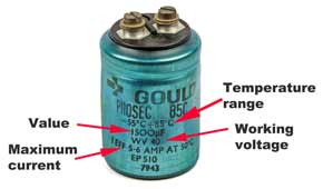
Electrolytic capacitor markings
There is a variety of different markings that are used for electrolytic capacitors to indicate their value, working voltage and possibly other parameters. Often the values are written directly on the can as there is space, but factors like tolerance, and sometimes working voltage may be coded.
The coding or marking system used will depend upon the type of capacitor, whether it is leaded or SMD and also the manufacturer, magnitude of the value, size of the component, etc..
Aluminium electrolytic capacitor lifetime
Aluminium electrolytic capacitors do degrade with time. Many electrolytics have a vent for allowing excess gasses to escape. This escape can result in the electrolyte drying out and the performance of the capacitor falling.
Also if aluminium electrolytic capacitors are left for a few years, then the oxide layer on the anode can dissipate. When this happens the capacitor needs to be repolarised. This can be done by applying a current limited voltage to the capacitor. Initially the, leakage current across the capacitor will be relatively high and then it will fall as the oxide layer forms.
It is also wise to take precautions to prolong the life of the capacitor. There are four golden tips to maximise the life of an aluminium electrolytic capacitor:
Run within its voltage limits: It is always wise to run any component with a good margin below the maximum ratings. Many companies state in their design rules that for electrolytic capacitors, they should only be run at about 50% of their maximum ratings to ensure optimum reliability. If the maximum limits are exceeded then leakage current levels will rise and there is the possibility of localised breakdown leading to an explosive failure of the component.
Keep within its current rating: In many applications an electrolytic capacitor will be required to provide high levels of ripple current. This is to be expected in applications like being used as a smoothing capacitor in a power supply. Ii is imperative to ensure that the capacitor can withstand the current being required from it. Check that the capacitor is operating within its current limits and is not becoming too warm in operation.
Never reverse bias the capacitor: When run under a reverse bias, the leakage levels will be very much higher than in the forward direction. Again this can lead to catastrophic breakdown and failure.
Keep temperatures down: Heat shortens the life of any aluminium electrolytic capacitor. A good rule of thumb is that every 10°C over 85°C will halve the life expectancy of the component.
Even though aluminium electrolytic capacitors have a life expectancy, this can be raised towards its maximum if these rules are followed and it is operated well within its ratings.
Reforming aluminium electrolytic capacitors
It may be necessary to re-form electrolytic capacitors that have not been used for six months or more. The electrolytic action tends to remove the oxide layer from the anode and this needs to be re-formed. Under these circumstances it is not wise to apply the full voltage as the leakage current will be high and may lead to large amounts of heat being dissipated in the capacitor which can in some instances bring about its destruction.
To reform the capacitor, the normal method is to apply the working voltage for the capacitor through a resistor of around 1.5 k ohms, or possibly less for lower voltage capacitors. (NB ensure that it has sufficient power rating to handle the capacitor in question). This should be applied for an hour or more until the leakage current drops to an acceptable value and the voltage directly on the capacitor reaches the applied value, i.e. virtually no current is flowing through the resistor. This voltage should then be continued to be applied for a further hour. The capacitor can then be slowly discharged through a suitable resistor so that the retained charge does not cause damage. Once reformed take care when using the capacitor to make sure that it has been fully reformed and is able to function correctly.
Electrolytic capacitor summary
ALUMINIUM ELECTROLYTIC CAPACITOR SUMMARY
PARAMETER
DETAILS
Typical capacitance ranges
1µF to 47 000µF
Rated voltage availability
From around 2.5V upwards - some specialised ones can have voltages of 350V and more.
Advantages
High capacitance per volume compared to most other types, relatively cheap when compared to other types of similar value.
Disadvantages
High leakage currents, wide value tolerances, poor equivalent series resistance; limited lifetime.