What Is a Transformer?
A transformer is an electrical device that transfers electrical energy from one circuit to another by electromagnetic induction (also called transformer action). It is used to step up or step down ac voltage.
Read -
How to Make a Simple Electric Generator
Components of a Transformer
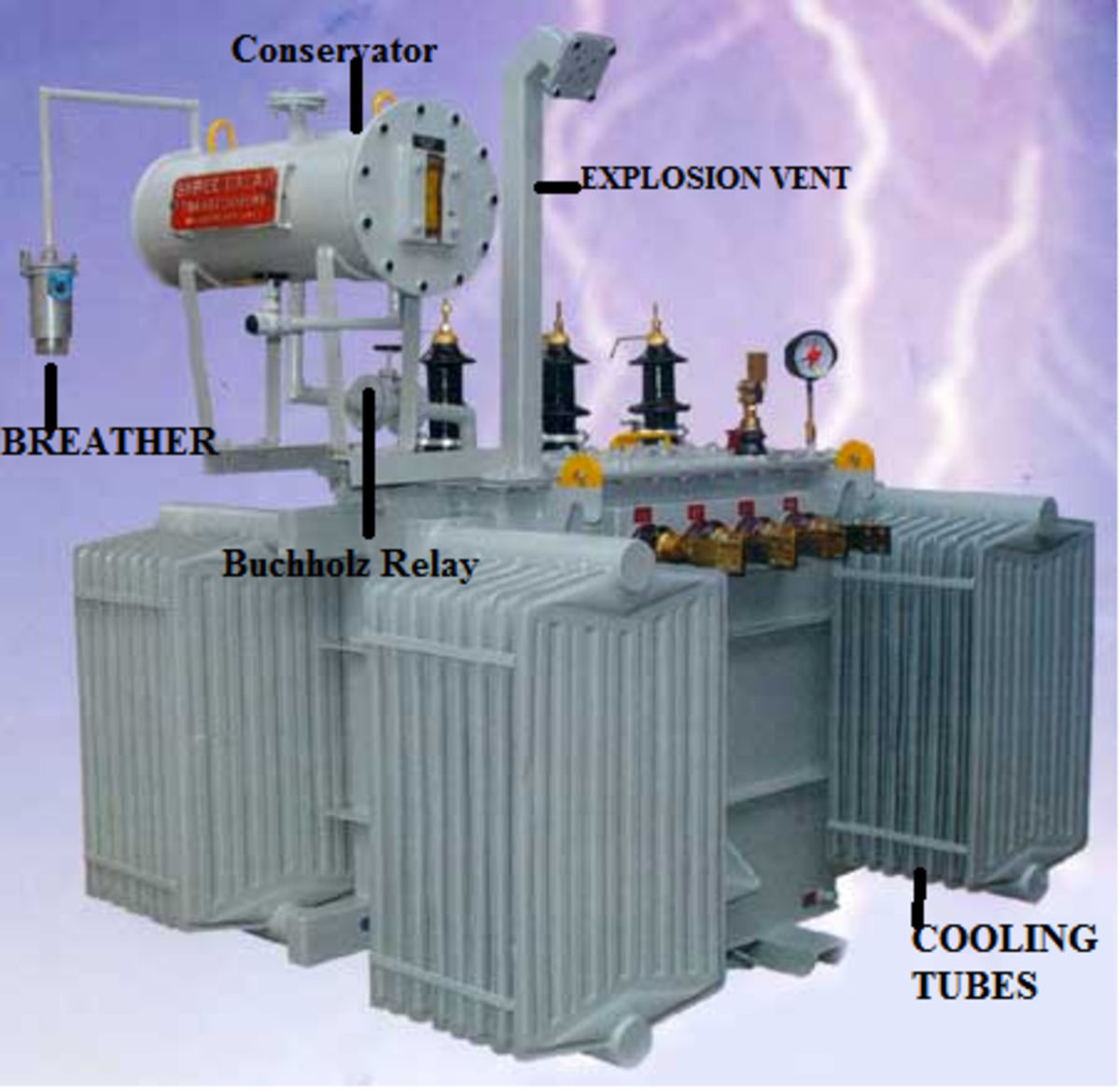
Basic Parts of a Transformer
These are the basic components of a transformer.
- Laminated core
- Windings
- Insulating materials
- Transformer oil
- Tap Changer
- Oil Conservator
- Breather
- Cooling tubes
- Buchholz Relay
- Explosion Vent
Of the above, laminated soft iron core, windings and insulating material are the primary parts and are present in all transformers, whereas the rest can be seen only in transformers having a capacity of more than 100KVA.
Core
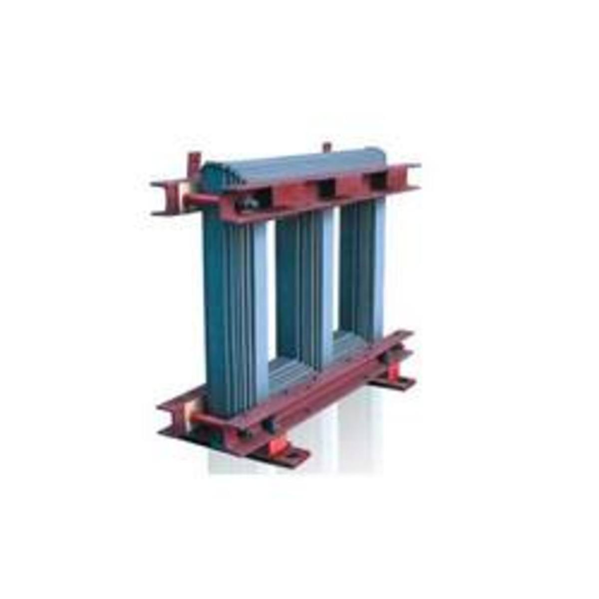
Core
The core acts as the support to the winding of the transformer. It also provides a low reluctance path for the flow of magnetic flux. It is made of the laminated soft iron core in order to reduce eddy current loss and Hysteresis loss. The composition of a transformer core depends on such as factors voltage, current, and frequency. The diameter of the transformer core is directly proportional to copper loss and is inversely proportional to iron loss. If the diameter of the core is decreased, the weight of the steel in the core is reduced, which leads to less core loss of the transformer and the copper loss increase. When the diameter of the core is increased, the vice versa occurs.
Why Are Windings Made of Copper?
- Copper has high conductivity. This minimizes losses as well as the amount of copper needed for the winding (volume & weight of winding).
- Copper has high ductility. This means it is easy to bend conductors into tight windings around the transformer's core, thus minimizing the amount of copper needed as well as the overall volume of the winding.
Winding
Two sets of the winding are made over the transformer core and are insulated from each other. Winding consists of several turns of copper conductors bundled together and connected in series.
Winding can be classified in two different ways:
- Based on the input and output supply
- Based on the voltage range
Within the input/output supply classification, winding is further categorized:
- Primary winding - These are the winding to which the input voltage is applied.
- Secondary winding - These are the winding to which the output voltage is applied.
Within the voltage range classification, winding is further categorized:
- High voltage winding - It is made of the copper conductor. The number of turns made shall be the multiple of the number of turns in the low voltage winding. The conductor used will be thinner than that of the low voltage winding.
- Low voltage winding - It consists of the fewer number of turns than the high voltage winding. It is made of thick copper conductors. This is because the current in the low voltage winding is higher than that of high voltage winding.
Input supply to the transformers can be applied from either low voltage (LV) or high voltage (HV) winding based on the requirement.
Read -
মাত্র 2200 টাকায় তৈরি করুন আপনার IPS
Insulating Materials
Insulating paper and cardboard are used in transformers to isolate primary and secondary winding from each other and from the transformer core.
Transformer oil is another insulating material. Transformer oil performs two important functions: in addition to insulating function, it can also cool the core and coil assembly. The transformer's core and winding must be completely immersed in the oil. Normally, hydrocarbon mineral oils are used as transformer oil. Oil contamination is a serious problem because contamination robs the oil of its dielectric properties and renders it useless as an insulating medium.
Parts of the Transformer
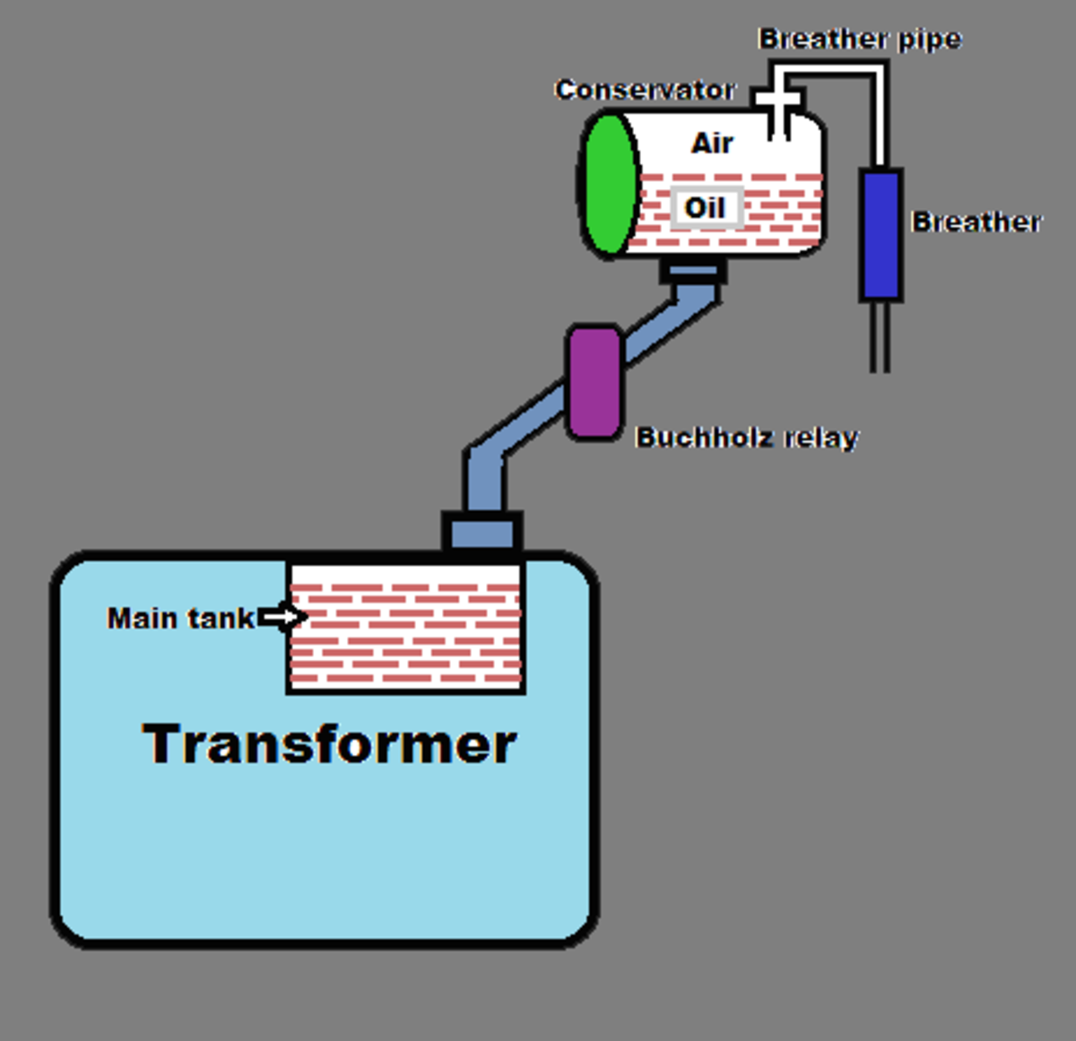
Conservator
The conservator conserves the transformer oil. It is an airtight, metallic, cylindrical drum that is fitted above the transformer. The conservator tank is vented to the atmosphere at the top, and the normal oil level is approximately in the middle of the conservator to allow the oil to expand and contract as the temperature varies. The conservator is connected to the main tank inside the transformer, which is completely filled with transformer oil through a pipeline.
Breather
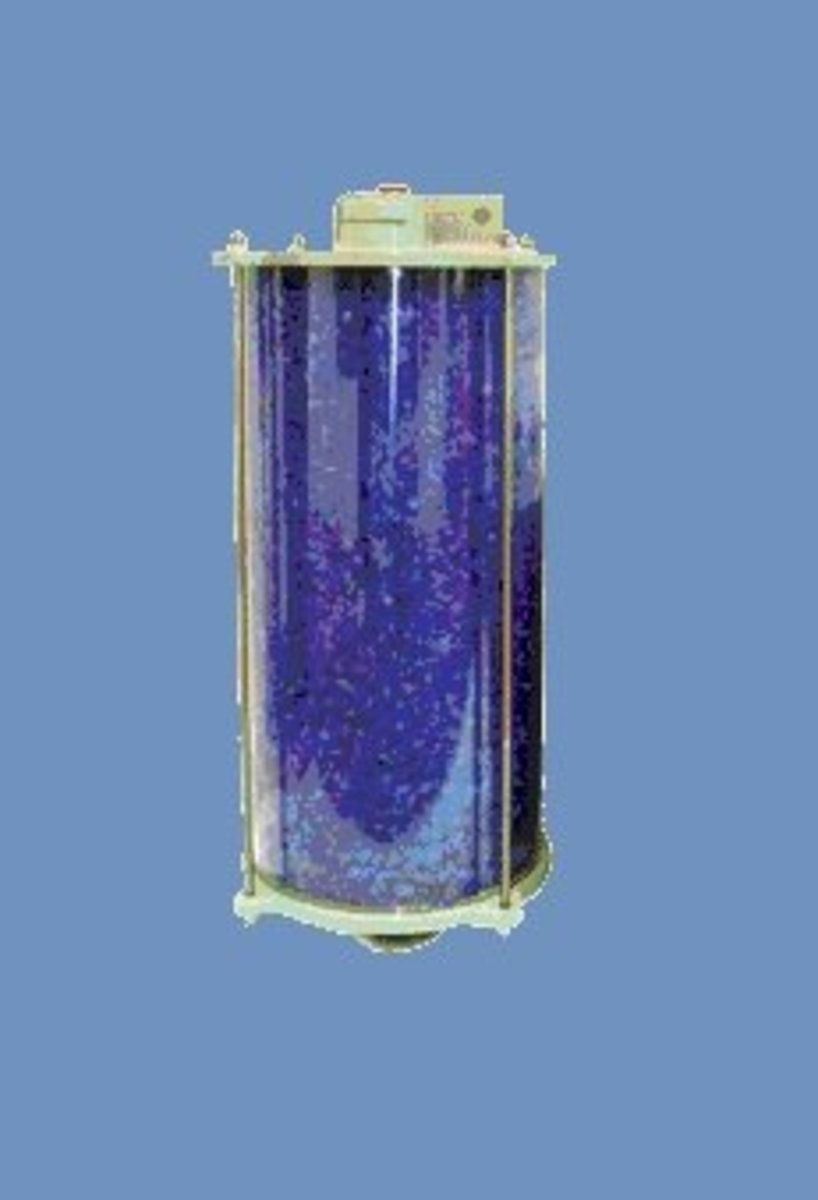
Breather
The breather controls the moisture level in the transformer. Moisture can arise when temperature variations cause expansion and contraction of the insulating oil, which then causes the pressure to change inside the conservator. Pressure changes are balanced by a flow of atmospheric air in and out of the conservator, which is how moisture can enter the system.
If the insulating oil encounters moisture, it can affect the paper insulation or may even lead to internal faults. Therefore, it is necessary that the air entering the tank is moisture-free.
The transformer's breather is a cylindrical container that is filled with silica gel. When the atmospheric air passes through the silica gel of the breather, the air's moisture is absorbed by the silica crystals. The breather acts like an air filter for the transformer and controls the moisture level inside a transformer. It is connected to the end of breather pipe.
Tap Changer

Tap Changer
The output voltage of transformers varies according to its input voltage and the load. During loaded conditions, the voltage on the output terminal decreases, whereas during off-load conditions the output voltage increases. In order to balance the voltage variations, tap changers are used. Tap changers can be either on-load tap changers or off-load tap changers. In an on-load tap changer, the tapping can be changed without isolating the transformer from the supply. In an off-load tap changer, it is done after disconnecting the transformer. Automatic tap changers are also available.
Cooling Tubes
Cooling tubes are used to cool the transformer oil. The transformer oil is circulated through the cooling tubes. The circulation of the oil may either be natural or forced. In natural circulation, when the temperature of the oil rises the hot oil naturally rises to the top and the cold oil sinks downward. Thus the oil naturally circulates through the tubes. In forced circulation, an external pump is used to circulate the oil.
Buchholz Relay
The Buchholz Relay is a protective device container housed over the connecting pipe from the main tank to the conservator tank. It is used to sense the faults occurring inside the transformer. It is a simple relay that is operated by the gases emitted during the decomposition of transformer oil during internal faults. It helps in sensing and protecting the transformer from internal faults.
Explosion Vent
The explosion vent is used to expel boiling oil in the transformer during heavy internal faults in order to avoid the explosion of the transformer. During heavy faults, the oil rushes out of the vent. The level of the explosion vent is normally maintained above the level of the conservatory tank.
More About Transformers
I have written a series of articles to help the reader understand power transformers. I've listed two here, and if you are interested in finding more, you can find them by clicking on my author profile at the top of this article.


